Power quality of commercial and industrial power systems
Power quality is a general term used to describe the degree of abnormality to several different electrical system characteristics. These characteristics are the frequency and amplitude of the voltage, the balance between phases on a three-phase system and the distortion level of the waveform. The characteristics that are important and what is considered an acceptable level of power quality varies from facility to facility.
Most of the older electro-mechanical equipment was robust and could handle minor power quality related issues with little or no effect on operations. But, due to the shift in the type of loads from electro-mechanical to electronic, power quality has become a real concern in all types of businesses. This includes hospitals, universities, commercial buildings and industrial facilities. Poor power quality results in random equipment malfunctions, data corruption, loss of process control, and heating of cables, motors and transformers.
Power source

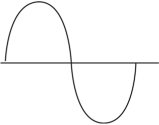
Figure 1
An ideal power source offers a continuous, smooth sinusoidal voltage, as shown in Figure 1.

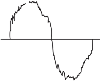
Figure 2
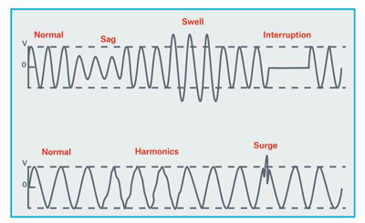
Poor power quality as shown in Figure 2 contains noise, harmonic distortion, voltage sags and swells, interruptions and voltage surge.
Causes of poor power quality
You might think that poor power quality is primarily the result of weather-related and utility-related disturbances. However, studies have shown that issues such as lightning, other natural phenomena, and utility operations, account for only a small portion of all electrical disturbances.
A large portion of electrical disturbances are from internal sources or from neighboring businesses that share the same building or are in close proximity. Internal sources can be fax machines, copiers, air conditioners, elevators, and variable frequency drives just to name a few.
Power quality issues

Courtesy of Advanced Protection Technologies
Typical power quality issues include: voltage transients (surge), harmonics, voltage sag and swell, voltage imbalance and interruptions.
Voltage transient (surge)
Description—A sudden high energy disturbance in line voltage typically lasting less than one cycle (< one second) which causes the normal waveform to be discontinuous.
Cause—Switching type loads
Issue—Data corruption, equipment malfunctions, equipment damage and process interruption.
Harmonic distortion
Description—Distortion of the current and voltage waveforms caused by the momentary on/off switching of nonlinear loads.
Cause—Elevators, HVAC equipment, rectifiers and welding machines.
Issue—Data corruption, data loss, computer-controlled equipment malfunctions, excessive heat and equipment failure.
Voltage sag/swell
Description—A decrease (sag) or increase (swell) in line voltage lasting at least 1/2 cycle (1/120 of a second) to several seconds.
Cause—Utility related events, starting and stopping of large loads.
Issue—If equipment is operated slightly outside the design envelope, random malfunctions and failure may occur. If the equipment is operated significantly outside the design envelope, the equipment will not operate and may fail prematurely. The effects are based on the length, magnitude and timing of the sag or swell.
Voltage imbalance
Description—Differing voltage levels on each leg of a three-phase system, typically < +/-2% of the average.
Cause—Large loads in a building such as HVAC equipment and elevators are three-phase loads. The small but numerous loads such as copiers, control equipment and computers are single-phase loads. Single-phase loads should be equally distributed among the three phases to prevent imbalance. Imbalance can also be caused by poor connections or blown fuses.
Issue—Depending on the level of imbalance, loads can operate erratically, not operate at all or fail.
Interruptions
Description—A significant or complete loss of voltage. The loss can be momentary or sustained.
Cause—Weather, utility equipment failures, internal faults or internal equipment failures.
Issue—A momentary interruption can damage computers and other electronically controlled equipment or disrupt processes. The damage can occur on both the loss and the re-energization of power. Electro-mechanical equipment is generally not affected by these brief outages. Sustained interruptions can last from hours to days. Contingency plans should be developed to address orderly equipment and process shutdown and restarts.
Solutions
Each occupancy will have a different sensitivity level to poor power quality and will have different sources of poor power quality. However, common to all businesses is the importance of a well-maintained electrical distribution and grounding system. The importance of these systems cannot be overstated. When addressing potential or actual power quality issues, the power and grounding system should be the first item addressed. This will ensure personnel safety, allow for the proper operation of surge protection devices, minimize the potential for excessive currents on neutral conductors, and provide a common reference plane for electronic equipment.
Once the power and grounding system deficiencies have been addressed, the next steps include: power quality walk-throughs, power quality inspections and surveys, and mitigation equipment.
Walk-throughs provide an overview of a facility from a power quality standpoint. In addition to housekeeping and the overall appearance of electrical equipment, items to note during a power quality walk-through include:
- Type of equipment that is installed
- Concentration of computer and electronic equipment
- Presence of welders, power factor correction capacitors, or variable frequency drives
- Heat discoloration of electrical equipment
- Communication and control wiring in close proximity to power wiring
- Condition of the grounding system
- Presence of surge protection installed on power and data lines
The conditions below are considered warning signs for potential power quality issues in a facility. These conditions do not guarantee a problem. A facility with these conditions usually has an increased likelihood of power quality issues.
- History of power-related issues
- Poorly maintained electrical system
- Failure of surge protection equipment
- Weather and utility disturbances common
- High concentration of electronic equipment
- Infrared surveys which identify current flow (heat) on grounding conductors and/or system neutrals
- Repeating and random equipment malfunctions, failures, tripped breakers or blown fuses with no identified causes
- Equipment running hot
- Frequent switching to backup power systems
- Lost data or data corruption
Based on the results of the power quality walk-through and the type of processes and equipment at the site, the following recommendations are common:
- Use infrared thermography to locate troubled areas. Not all power quality related issues will cause hot spots. Loose connections, harmonics and undervoltage will cause an increase in the operating temperature of equipment.
- Conduct a power quality inspection and survey using a properly trained and experienced power quality contractor. The results of the inspection and survey should be reviewed with trained and experienced power quality engineers.
- Perform a power quality study if an expansion is planned or a large load is being added. This study should be completed during the design of the expansion or during the specification process of the new equipment installations.
Power quality inspections and surveys identify the types of problems, the extent of the problems, and the potential solutions. Power quality inspections and surveys should only be performed by qualified power quality contractors. In many commercial or light industrial type businesses, only a few loads are affected by power quality issues and only a few loads are susceptible to poor power quality. By identifying these loads during a survey, targeted mitigation techniques can be utilized.
A power quality survey is the monitoring and recording of the power system supplied to a building or specific area of a building. It is important to measure power continuously over an extended period of time such as days or weeks. This will capture all of the intermittent event. Due to the special knowledge needed to identify power quality related issues, it is recommended that only electricians trained in the use of power monitoring instruments be utilized. The equipment should be capable of recording very fast events (less than one cycle) and have data storage capabilities. Since it is difficult to monitor all points simultaneously, selecting the best points to monitor is extremely important. This should be done based on the areas of concern that were identified during the inspection. The equipment must be monitored in its normal operating environment. Do not perform a power quality survey during a shutdown.
The review of the data from the survey will determine the type and severity of the problems and assist in recommending mitigation techniques. The data review should be performed by qualified and experienced power quality engineers.
Prior to selecting any type of mitigation equipment, the power quality deficiencies that are responsible for operational issues and failures must be clearly identified. The next step is to estimate the costs of the power quality related issues. This aids in a budget for the project.
A wide variety of power quality correction products is available utilizing a range of technologies and providing a range of protection. Common mitigation techniques include surge protection devices, isolation transformers, voltage regulators, motor generators, standby power supplies, uninterruptible power supplies and harmonic filters. Each technique has advantages and disadvantages and should be applied based on the discovered problems.
This list defines different types of mitigation techniques available, but it is not a complete list.
Surge Protection Devices (SPD)
Function—Diverts surge events to ground.
Description—A device connected between line and ground which has high impedance at normal frequency system voltage levels and very low impedance at higher than normal voltage levels. Because of this low impedance, the SPD acts as a shunt to ground for voltage surge events. Devices vary in their surge current-handling capability and voltage-limiting capability. Since devices have different voltage and current capabilities, a multi- level approach is required to protect against surge events. The multi-level approach is also known as zones of protection. Each zone experiences a different level of surge event and therefore the SPD should be sized appropriately based on the zone. In general terms, the zones of protection are the service entrance line, the remote distributed panelboards, and at the equipment points-of-use.
Communications and data equipment are also vulnerable to surges. Special surge protectors are available for line protection of this equipment.
Many types of equipment claim to have built-in surge protection. But these are often inexpensive varistors. These devices may or may not provide sufficient protection. They should be supplemented by the field installed units for complete surge protection
Isolation transformers
Function—Isolation transformers attenuate common-mode disturbances on the power supply conductors, provide a local ground reference point and allow for voltage output adjustments using internal winding taps.
Description—A transformer with special windings utilizing a grounded electrostatic shield between the primary and secondary. This grounded shield provides attenuation of high-frequency noise. Isolation transformers may step the voltage up or down (i.e., 480v to 208v) or be used for isolation only with no output voltage change (208 V in and 208 V out).
Voltage regulator
Function—Provide a constant output voltage level for a range of input voltages.
Description—A variety of voltage regulation techniques are available, such as ferro resonant transformers, electronic tap-switching transformers, and saturable reactor regulators.
Motor generator
Function—Provides voltage regulation, noise/surge elimination, voltage distortion correction and electrical isolation between the electrical system and the connected equipment.
Description—A separate motor and an alternator (generator) are interconnected by a rotating shaft and coupling. Typically, the utility is the power supply for the motor which drives the generator to produce clean power.
Standby power supply
Function—An inverter and battery backup power system operating as an outage protection system. In normal mode, the inverter is in a standby mode and the load is directly supplied from the input power source. On a loss of input power, the load is switched to the battery supply. There is a momentary break in power when the transfer to and from input power occurs.
Description—Usually comprised of a solid-state inverter, battery, and battery charger.
Uninterruptible power supply (UPS)
Function—Maintain uninterrupted supply of regulated voltage for a period of time after a power failure.
Description—A variety of technologies exists. The two common types are rotary and static. A rotary unit consists of a motor generator set with a short ride through capability. A static unit utilizes power electronics and a battery string or other energy storage means as a source of energy during loss of input power. These depend on properly maintained batteries. The battery system is sized based on the load and duration of required time.
Other types include combinations of rotary and static units or UPS systems supplemented with engine driven generators for extended outages.
The design of the backup power supply capability should reflect the criticality and size of the loads to be supplied. Redundancy should be in consideration for installations with significant power loss consequences. Each element of the backup power scheme needs to be viewed as a point of failure. If appropriate the design should provide for functional duplication of each system component.
Harmonic filters
Function—Acts to reduce the level of harmonic distortion on a power system.
Description—Harmonic filers should be specifically designed to suppress the offending harmonics determined during the monitoring and analysis study. Harmonic filters may be available from equipment manufacturers that manufacturer electrical equipment known to create harmonic distortions on the power lines.
To learn more about Hanover Risk Solutions, visit hanoverrisksolutions.com
Copyright ©2011, 2015, 2017 The Hartford Steam Boiler Inspection and Insurance Company. All Rights Reserved. Used with permission of The Hartford Steam Boiler Inspection and Insurance Company
The recommendation(s), advice and contents of this material are provided for informational purposes only and do not purport to address every possible legal obligation, hazard, code violation, loss potential or exception to good practice. The Hanover Insurance Company and its affiliates and subsidiaries ("The Hanover") specifically disclaim any warranty or representation that acceptance of any recommendations or advice contained herein will make any premises, property or operation safe or in compliance with any law or regulation. Under no circumstances should this material or your acceptance of any recommendations or advice contained herein be construed as establishing the existence or availability of any insurance coverage with The Hanover. By providing this information to you, The Hanover does not assume (and specifically disclaims) any duty, undertaking or responsibility to you. The decision to accept or implement any recommendation(s) or advice contained in this material must be made by you.
LC FEB 2019-409
171-9262 (1/19)
